COMPASS Polarized Target


Photos status April 20 2007.

Polarized Target Wiki.

Polarized Target Elog.

Target polarization data repository.

Target cryogenics data repository.

Checklist archive.

Programs for analysing NMR-signals and cryogenics data.

Small utilities: dcsread, ptread, shiftlist and rfindcalc.

2015

  • Minutes from weekly meetings 2015.

    2014

  • Minutes from weekly meetings 2014.

    2013

  • Minutes from weekly meetings 2013.
  • ptread HOWTO.

    2012

  • Minutes from weekly meetings 2012.

    2011

  • Minutes from weekly meetings 2011.
  • Shifts 2011.

    2010

  • Minutes from weekly meetings 2010.
  • Electronic log book 2010.
  • Target shifts with small changes and additions to the official shift list. Also target week coordinations are included. Simple text file from the shift list.

    2009

  • Minutes from weekly meetings 2009.

    2008

  • Minutes from weekly meetings 2008.

    2007 Run

  • Run 2007.
  • SPS 2007.

  • NMR files on web page by Takuma.
  • Electronic log book 2007.
  • First target shifts.
  • Target shifts.
  • End of run shifts.

  • Minutes from weekly meetings 2007.

  • 40 mm NH3 target 2007 v0.1 in pdf file and in black and white.
  • 40 mm NH3 target 2007 v0.1 in png file and in black and white.

    2006 Run

  • Preliminary polarization P1B - P3B.
  • Polarization P1B.
  • Polarization P1C.
  • Polarization P2A.
  • Polarization P2B.
  • Polarization P2C.
  • Polarization P3A.
  • Polarization P3B.
  • Run 2006.
  • SPS 2006.

  • Electronic log book 2006.
  • Shift list 2006.
  • Minutes from weekly meetings 2006.

  • Polarized Nucleon Targets for Europe in the 6th European Framework Program (Rech).

  • Takeshis report on target packing factor simulations to understand the geometrical cuts used in the asymmetry analysis.
  • Pauls report on spin temperature analysis of the highest polarization values 2001 - 2004.

  • NMR tools HOWTO.

  • NMR field maps.

    2005

  • Minutes from weekly meetings 2005.

  • Polarized Nucleon Targets for Europe in the 6th European Framework Program (Miltenberg).
  • XIth International Workshop on Polarized Sources and Targets November 14-17, 2005, Tokyo, JAPAN.

  • Yuris talk on cavity testing April 14.
  • Mauricios talk on Mainz Microtron (MAMI) microwave system August 16.
  • Roberts report on polarization data quality in run log book 2002 - 2004.
  • Jaakkos talk on cavity feeding October 6.
  • Jaakkos poster in PST05 November 14.

  • Norihiros photos on dilution cryostat and new 180 mrad superconducting magnet December 5.

    2004 Run

  • Preliminary polarization P1A - P2C.
  • Polarization P1A.
  • Polarization P1B.
  • Polarization P1C.
  • Polarization P2A.
  • Polarization P2B.
  • Polarization P2C.
  • Run 2004.
  • SPS 2004.
  • Field rotation times 2004.
  • Histogram of field rotation times 2004.

  • Electronic log book 2004.
  • Shift list 2004.
  • Minutes from weekly meetings 2004.

  • Aoibhinns report on new mixing chamber.
  • Drosoulas calculations on NMR coil field and polarization distribution.
  • Isabels analysis of 2004 TE-calibration signals.
  • Isabels talk on 2004 TE-calibration July 29.
  • Jaakkos technical board talk January.
  • Jaakkos offline talk.
  • Jaakkos talk on PT removal September.
  • Kaoris collaboration meeting talk August 27.
  • All Kaoris talks, plots and reports 2001 - 2004.

    2003 Run

  • Preliminary polarization P2A - P2E.
  • Polarization P2A.
  • Polarization P2B.
  • Polarization P2C.
  • Polarization P2D.
  • Polarization P2E.
  • Run 2003.
  • SPS 2003.
  • Field rotation times 2003.
  • Histogram of field rotation times 2003.
  • Preliminary polarization 2003.

  • Electronic log book 2003.
  • Shift list 2003.
  • Shift histogram 2003.
  • Minutes from weekly meetings 2003.

  • Kaoris collaboration talk in February.
  • Jaakkos collaboration talk in April.
  • Jaakkos collaboration talk in October Lisbon.
  • Jaakkos talk October in Bad Honnef.
  • Jaakkos collaboration talk in December.
  • Isabels polarization analysis 2003.
  • Kristins report on target PLC.
  • Kristins diagrams on target PLC.

    2002 Run

  • Preliminary polarization P1B - P2C.
  • Polarization P1B.
  • Polarization P2A.
  • Polarization P2B.
  • Polarization P2C.
  • Run 2002.
  • SPS 2002.
  • Field rotation times 2002.
  • Histogram of field rotation times 2002.

  • Minutes from weekly meetings 2002.

  • Jaakkos collaboration talk in November.

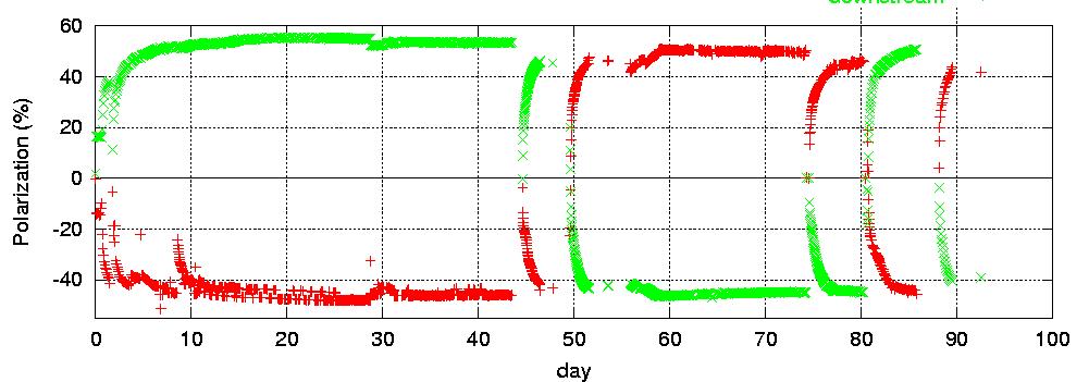
    The target operated well from 18th of June to 18th of September. There were two transverse polarization mode periods with microwave polarization reversal in the middle. First of them was from 3rd of August to 12th of August. Second one was from 11th of September to 18th of September. In the beginning the upstream target cell had negative polarization while the downstream target cell had positive polarization. After the microwave polarization reversal on 6 - 8th of August the upstream target cell had positive polarization while the downstream cell had negative polarization. During the run the polarization was lost 4 times due to loss of magnetic field. In the run 2002 about 405 eight hour target shifts were done. 342 of these were during the beam time, 42 before and 21 after. Thanks to the about 50 persons from the collaboration who took part in the target shifts. Preliminary polarization 2002.. Online average polarization 2002..

    2001 Run

  • Preliminary polarization P2A - P2B.
  • Run 2001.
  • SPS 2001.

  • Minutes from weekly meetings 2001.

  • Jaakkos collaboration talk in January.
  • Jaakkos collaboration talk in March.
  • Jaakkos TB talk in May.
  • Jaakkos collaboration talk in June.

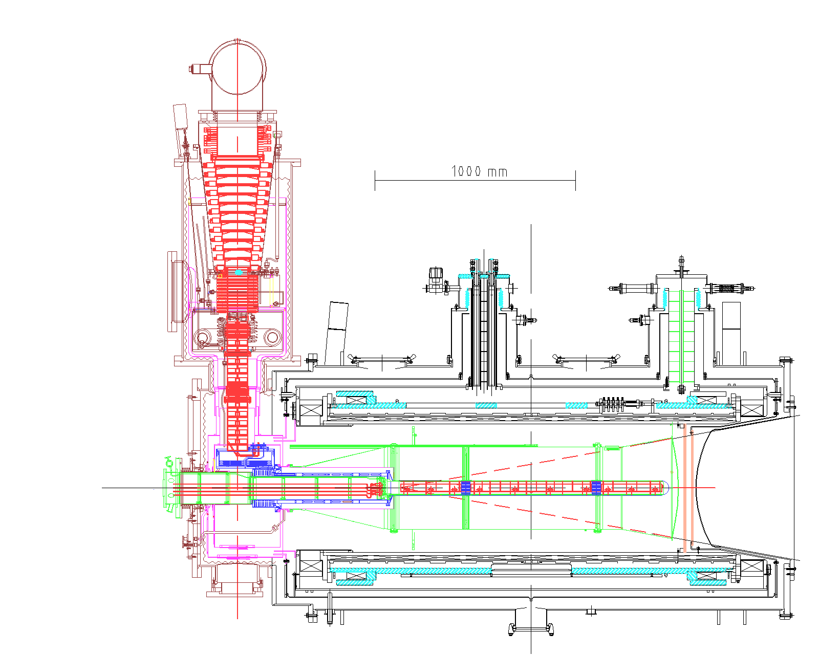
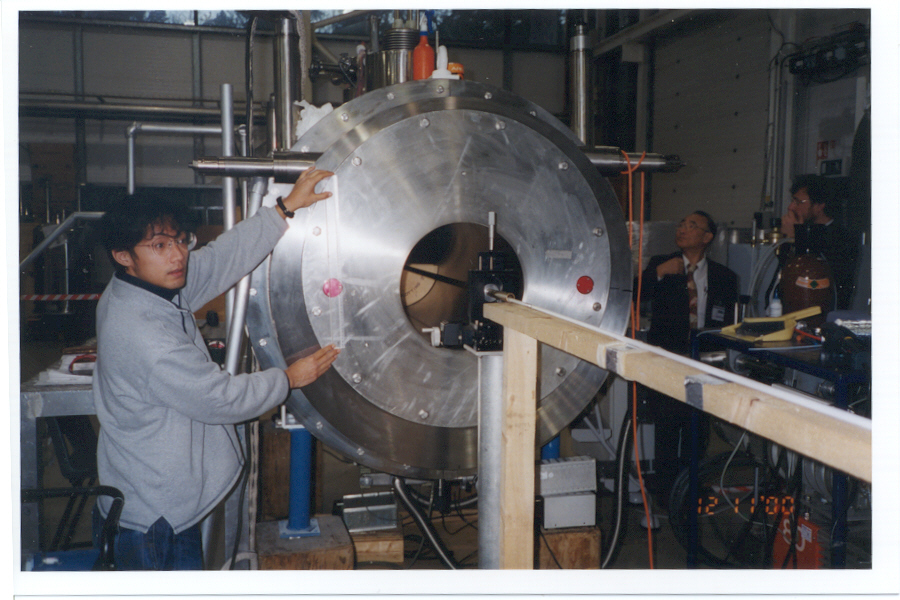
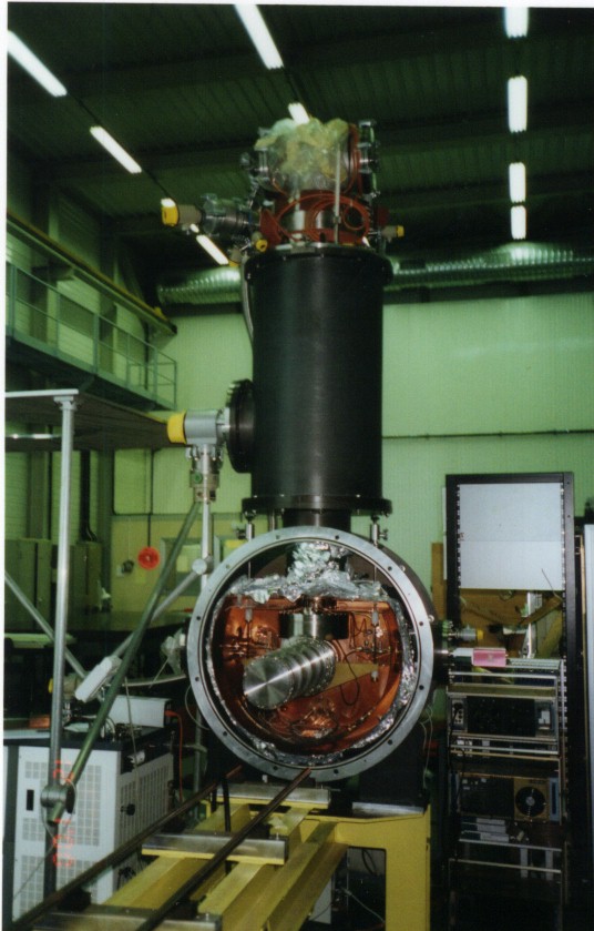
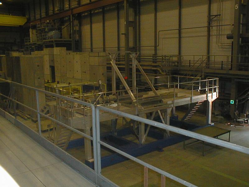
    For the year 2001 the old magnet from the SMC experiment was installed on the platform. A new microwave cavity fitting inside the magnet 265 mm diameter bore was manufactured (May - Jul 2001). The cavity has 0.5 mm down stream end window made of copper. The two target halves are separated by a microwave stopper made from 0.1 mm copper foil. The mixing chamber is the same as in the SMC experiment. With the two target cells (each 60 cm long and diameter 3 cm) separated by 10 cm distance in the center of the solenoid this leads to an acceptance of 69 mrad.

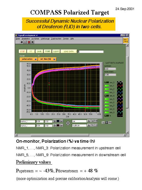
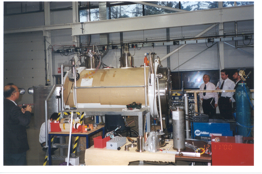
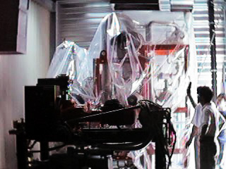
    Big effort between CERN and Saclay was needed to get the magnet work in very short time (May - Aug 2001). The target material 6LiD from Bochum was successfully loaded inside the mixing chamber (Aug 2001). The first polarization runs (Sep 2001) have resulted to negative and positive polarizations from 45 to 50 % ( zipped ppt-file ). To confirm these values more NMR data is being collected.

    2000 Preparations

  • Jaakkos collaboration talk in April.
  • Jaakkos collaboration talk in July.
  • Jaakkos TB talk in October.
  • Jaakkos TIS talk in October.

    Introduction

    COMPASS uses solid polarized proton and deuteron targets in the muon program. The target material is either ammonia or 6LiD. The nuclear spins are polarized with dynamic nuclear polarization (DNP), based on microwave saturation of impurity electron spins near their paramagnetic resonance in a 2.5 T longitudinal field. The two target cells have the length of 60 cm and a diameter of 3 cm, and they are polarized in opposite directions.

    Magnetic poles of the SMC and COMPASS solenoids

    The magnetic poles of the solenoid were measured with a compass. The photos of the measurements 2003 - 2004 are here and for 2006 here. The 2007 photos.

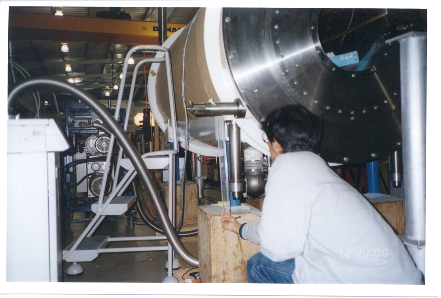
    A test solenoid was used to determine how the magnetic poles correspond to the magnetic field direction. The photos are here.

    The measured magnetic poles for positive solenoid current. The field direction is determined inside solenoid.
    Date Upstream Downstream Field direction
    2002 July 22 South North ups <- dws
    2003 July 3 South North ups <- dws
    2004 June 11 South North ups <- dws
    2006 July 26 North South ups -> dws

    The Canadian Geological Survey definition of the North Magnetic Pole is here

    Magnetic poles of the target spin magnetization

    The spin magnetization poles can be determined from the known solenoid current sign and from the sign of the polarization as follows:

    Spin magnetization poles for positive and negative currents. First is the upstream pole and the second is the downstream pole of the target cell. Also the direction of spin is shown for nuclei with positive gyromagnetic ratio, e.g. deuterium.
    positive polarization negative polarization positive polarization negative polarization
    positive current 2002 - 2004 South-North North-South ups <- dws ups -> dws
    negative current 2002 - 2004 North-South South-North ups -> dws ups <- dws
    positive current 2006 North-South South-North ups -> dws ups <- dws
    negative current 2006 South-North North-South ups <- dws ups -> dws

    Oxford Magnet

    Due to the requirement of larger acceptance of 180 mrad a new superconducting magnet has been ordered from Oxford Instruments. The details of the magnet design were fixed in March 97. The magnet is expected to provide a longitudinal field of max. 2.7 T with 100 ppm inhomogeneity over the target volume and a vertical 0.6 T field with 9% inhomogeneity. The magnet is being tested at Oxford Instruments (Jan - Sep 2001). Unfortunately in testing phase unexplained quenches were observed at field less than required by magnet specifications. Oxford Instruments is studying the reason for these quenches to understand what actions are needed to make operation stable (Apr - Sep 2001). Installation at CERN including field mapping inside magnet and adjustment of trim coil currents with and without spectrometer magnet SM1 is expected to take 8 - 10 weeks. A calculated field map close to magnet is already available. See Nagoya Polarized Target Group.

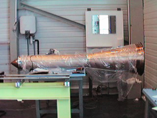
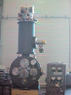
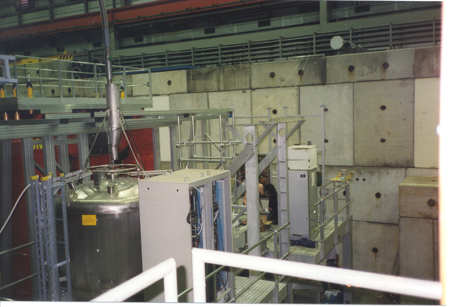
    Here is a side view of the magnet.. The solenoid is powered with the Danfysik power supply while for the dipole coil we use the old Drusch power supply from SMC. The magnet has a Quench Back Heater system to cause a forced quench if quench in some part of the solenoid is detected. The burst disk gives the ultimate safety in sudden evaporation of LHe. The suspension system will keep the solenoid in place even when SM1 is powered and a large torque is acting on the coil. The magnet is connected to the dilution cryostat from the upstream flange.

    System integration between Oxford Instruments magnet and CERN facilities is being discussed. Here is information about the old SMC cryogenic system. COMPASS will use the old Drusch power supply for the dipole magnet and the safety interlock unit to prevent energizing of dipole if solenoid has more that 1/3 of its maximum field.

    Safety issues concerning the magnet installation have been discussed with TIS division . Mainly this concerns the pressure vessel safety code D2, magnetic field and operation safety.

    Dilution Refrigerator

    For the Oxford magnet the main modification to the SMC cryostat was the new microwave cavity. Otherwise the cryostat is the same. The beam goes in from here. Here is a schematic diagram of dilution cryostat with the magnet.

    The conical cavity inside the magnet has 100 um thick Cu foil at its end. Such a thin foil can not stand any practical pressure difference. Thus the cavity vacuum will be shared with Oxford magnet vacuum. This is different from the SMC experiment where the cavity was isolating the vacuum outside of the mixing chamber from magnet vacuum and worked as an extra protection in case that the glass fiber mixing chamber for some reason starts to leak. This could happen for example when the target material is being loaded. In this procedure there are mechanical forces to the mixing chamber.

    Since the muon beam is now focused to 30 mm diameter a smaller diameter of mixing chamber can be used. The volume of target material and helium surrounding it was the same for the SMC target. Thus the mixing chamber could be made 
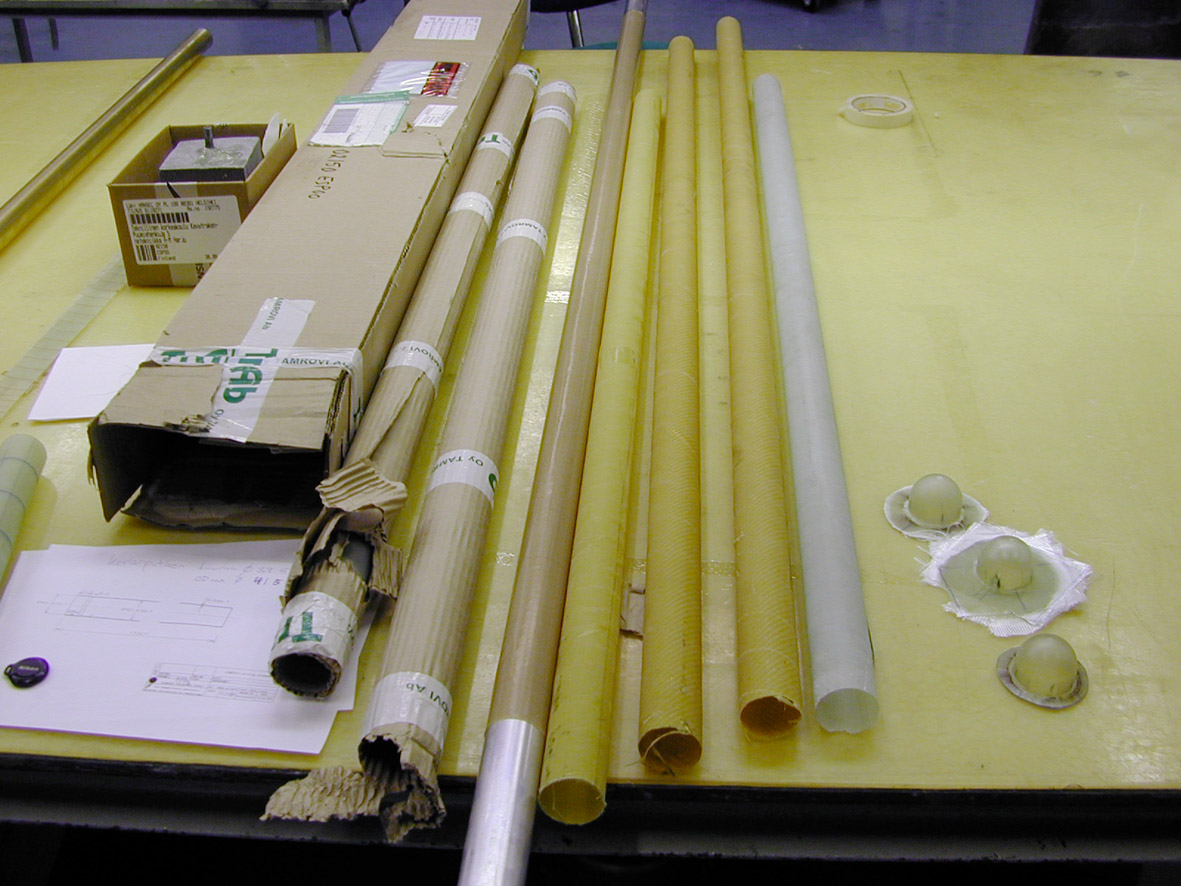
to 45 mm in diameter. Thus a new glass fiber mixing chamber is being prepared. It has to be leak and pressure tested before it can be accepted. In normal operation the mixing chamber has to stand + 1 atm pressure. Leak testing of the new mixing chamber showed no leaks at room temperature (Sep 2000). Unfortunately in cooling down with LN2, two of the three glass fiber tubes started to leak. They were inspected after opening the test vacuum vessel and cracks were seen close to the end hemisphere.

    Leak and flow tests at room temperature showed (Dec 1999 - Jan 2000) that the cryostat is ok. One epoxy feed through from still was leaking to vacuum, but was easy to fix. A cryogenic leak test was be done in March 2001. The leak rate stayed at 10^-9 mbar l/s and isolation vacuum pressure below 10^-7 mbar during the one week period that the cryostat was cold. The minimum temperature obtained was only about 0.25 K due to missing 4 K radiation shield, i.e. only 80 K radiation shield was used. More careful technical run will be needed to verify proper operation of heat exchangers and to check thermometer calibration.

    Pumping System

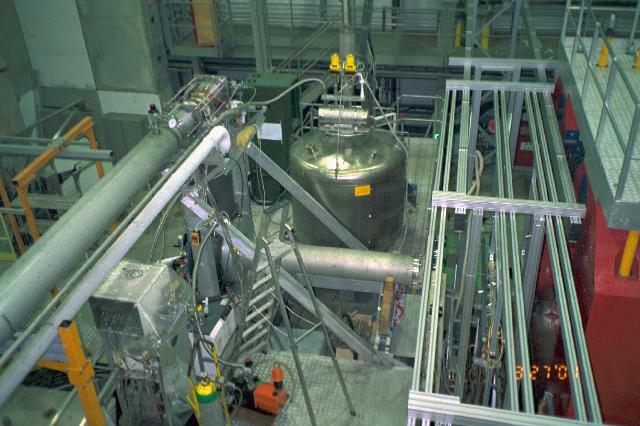
    Due to new focusing of the muon beam from 50 mm diameter to 30 mm diameter, the polarized target had to be moved 20 m down stream compared to its position in the SMC experiment. A new pump hut had to be constructed and new pumping lines welded.

    The cooling water circuit for the pumps and pressurized air for electro-pneumatic valves are both ready (June 2000). The roots blowers were tested (Feb - Mar 2001). The test included purging by pumping dry nitrogen for several days, helium leak tests and pumping of helium gas for a week to see how much air impurity is accumulated into LN2 trap. AT/ECR/Cryolab was responsible of the testing.

    4He pumps were tested after the roots blowers. The 4He pumping and exhaust tubes were installed with bypass and overpressure valves and manometers.

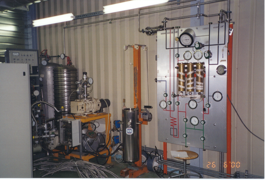
    The control panel has new purifier cartridges and the LN2 trap new charcoal in it. Both are kept under vacuum when the dilution cryostat is not run. The trap and purifiers were also leak tested before they were put in to use.

    The 3He tanks were connected to control panel. A new hermetic pump from Alcatel 2033H was bought for reliable recovery of 3He (which has value of about 250 kCHF) in all conditions. Mixture inventory was made 15th of March 2001 by AT/ECR/Cryolab. 1387 l NTP of 3He gas was found. In addition we have 7198 l NTP of 4He gas.

  • Diagram of the pumping system status 2004 (A1 size PDF file).
  • PLC main page (only from CERN). Slow and needs right version of Java Runtime Environment.
  • PLC still heater interlock.
  • PLC LN2 trap.
  • PLC pumps.
  • PLC pressures.
  • PLC microwave interlock.
  • PLC LHe and LB2 levels.
  • PLC valves.
  • PLC flows and temperatures.

    Cold Box

    Has been tested to give 75 l/h of helium liquid to the 2000 l buffer dewar. This has be boosted to 100 l/h or more, with LN2 cooled on line purifier (Aug 2001). The cold box was upgraded with parts coming from LEP experiment (Jan 2001). Oxygene level of returning helium gas was measured to be on the level of 10 ppm when both the magnet and dilution cryostat were operated simultaneously (Aug 2001).

    The cryostat needs 15 - 40 l/h depending on the 3He flow and the magnet about 10 - 20 l/h at full field. The helium recovery goes back to the cold box. In case of a quench the evaporating helium gas is vented to the experimental hall through the over pressure valves of SMC magnet.

    See status of COMPASS cold box for information about liquid helium available for target.

    Liquid nitrogen

    Polarized target needs liquid nitrogen for precooling of the magnet. The precooling of SMC magnet takes about 5 days. When the target material is being loaded, it is stored into a liquid nitrogen bowl at target loading platform. During the operation of the dilution cryostat the LN2 is used in the cold trap to prevent impurities coming from roots blowers from blocking the 3He return line inside cryostat.

    NMR Polarization Measurement

    The old Liverpool Q-meters are used. The NMR-coils embedded into target material in 2001 were saddle coils 10 mm diameter and 70 mm long for deuterium target. Each target cell had 5 coils. The coils were made from 1.6 mm diameter CuNi tube, which was covered with a PTFE tube. To improve the target material packing factor the coils were mounted on the outside of the target cells for the runs 2002 - 2004. Four coils were used on each target cell. In addition there was one or two coils embedded into the target material close to the microwave stopper. The coils were made of 1.0 mm diameter resistive CuNi tube. Saddle shape was used with length of 60 mm and diameter of 32 mm. For more info see Kaoris documentation. To analyse the NMR data you can check the NMR tools HOWTO.

  • Photos of the Liverpool Q-meters.

    Microwave System

    Main concern was the new very thin microwave stopper. In the SMC cryostat the stopper was made of several 1 mm copper plates. It had about 3 kg of copper. Such amount of material could not be accepted for the COMPASS. Thus it was important to study how well a thin 100 um foil could separate the two target halves. The results were much worse than expected from simple skin depth (about 1 um at 70 GHz for Cu). The reason in tests turned out be poor contact of the foil to the surrounding cavity. Finally the leak was around 0.1 uW level, which was also the measurement limit. It is not possible to measure better isolations than this with the microwave table. We would need more powerful microwave source or more sensitive power meter. For more info see Nagoya Polarized Target Group.

    Target Platform

    Target platform. Electricity and pressurized air was available on the platform from Jan 2001. Connections and tubes for normal and demineralised cooling water have been installed. Demineralised cooling water was available from Apr 2001. The LHe transfer line to buffer dewar and support arm for cables are both installed and ready.

  • Platform power September 2005.
  • Platform power January 2006.

    Control Room

    The control room has all the racks inside. The instrumentation and cabling for flow controllers, flow meters, pressure transducers, pressure gauges, resistance and diode thermometers is ready and operational. Most important parameters are captured to the "multireg" chart recorder, which also generates alarms if certain parameters go outside their normal operation range (roots backpressure, LN2 trap level, isolation vacuum, evaporator level).

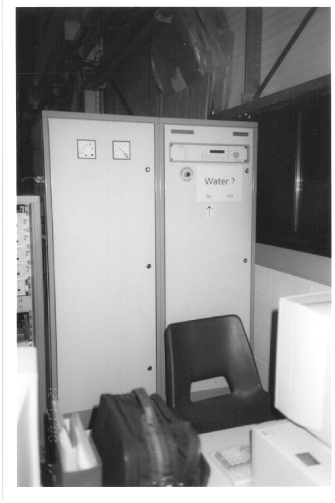
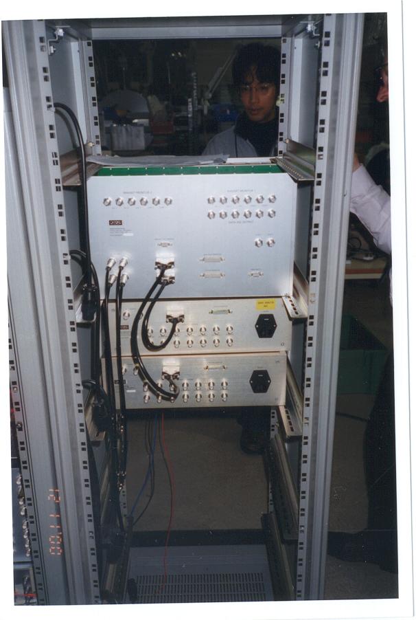
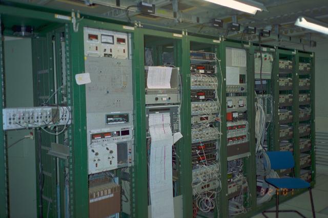
    The control software for the target cryostat and NMR is done with LabVIEW in Windows NT. It controls and monitors cryostat and NMR system through GPIB bus and a VME crate. For the NMR a dedicated PC is installed. During the cool down of the cryostat the PC was used to record the different parameters of the cryostat. The present status of the target can be seen on the web. For the SMC magnet the old Sun system is used for the control.

    Target Materials

    See Bochum Polarized Target Group. They are working on 6LiD.

    Experimental hall

    See COMPASS web camera if you want to know what is happening right now in the experimental area.

    Safety valves

  • Inventory February 2003.
  • Inventory April 2005.
  • Leak test September 2005.
  • Inventory February 2007.
  • Leak test February 2007.
  • Inventory March 2009.
  • Leak test March 2009.

    Calculations

  • Sharipov's gas flow in tubes.

    Useful links

  • Adixen(former Alcatel Vacuum Technology)
  • Agilent Technologies(former HP).
  • Amplifonix
  • Cryo Diffusion
  • Danfysik
  • Emerson & Cuming
  • ET System electronic
  • GoodFellow
  • Laboratory of Lightweight Structures
  • Lakeshore
  • Macom
  • Mini-Circuits
  • Norit activated carbon
  • Oxford-Danfysik
  • Oxford Instruments Cryospares
  • Pfeiffer vacuum
  • Picowatt
  • Praxair
  • Precision tube
  • Ziehl industrie-elektronik GmbH+Co

    SMC target

    EDMS drawings


    Contributions

    (tell me the missing names)

    Bielefeld

    G. Baum
    F. Gautheron
    R. Gehring
    Y. Kisselev

    Bochum

    W. Meyer
    G. Reicherz
    S. Goertz
    A. Meier
    I. Llorente-Garcia

    AT/ECR/Cryolab

    L. Dufay
    A. Vacca
    L. Mao
    G. Vandoni
    C. Policella
    J-M Rieubland
    T. Niinikoski

    Helsinki

    P. Berglund
    J. Koivuniemi

    Nagoya

    Yamagata

    I. Daito
    N. Doshita
    T. Hasegawa
    N. Horikawa
    S. Ishimoto
    T. Iwata
    K. Kondo
    T. Matsuda
    N. Takabayashi

    Prague Joined Czech Group (JCzG)

    Michael Finger
    Miroslav Finger
    S. Neliba
    A. Srnka

    Saclay

    J. Ball
    J-M Le Goff
    A. Magnon
    C. Marchand


    This page was updated July 6 2020 by Jaakko Koivuniemi.