Details of the SMC dilution refrigerator
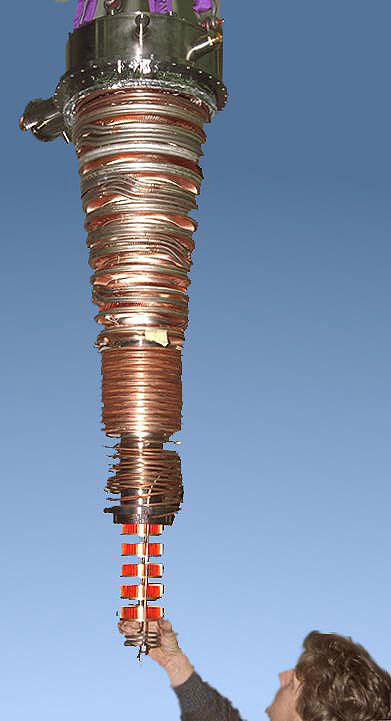
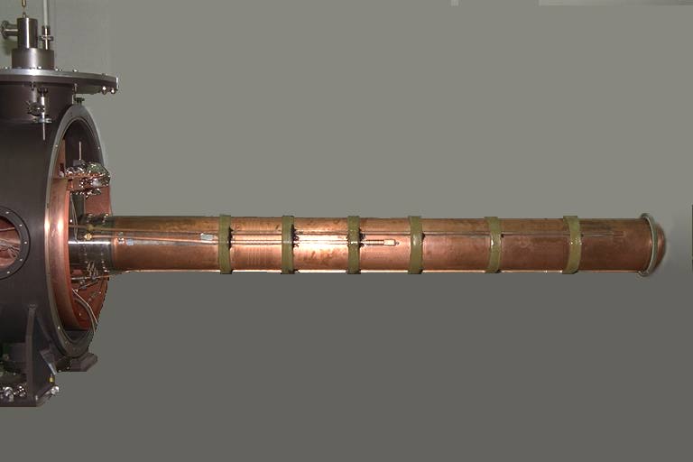
The refrigerator for the SMC twin solid polarized target at CERN is by far the largest dilution refrigerator in operation.
Performance and data
- The 2.5 liter, 1.5 m long target is loaded cold, horizontally into the mixing chamber.
- A cooling power of 400 mW at 300 mK is available for dynamic nuclear polarization.
- Proton and deuteron targets are polarized to +/-94% and +/-46%, respectively.
- The base temperature of 30 mK enables rotation of the polarization vector without losses.
The geometry of the dilution refrigerator is dictated by the requirements of the scattering experiment and the handling of the target material. The chosen geometry provides minimum amount of material in the muon beam path to reduce multiple scattering and bremsstahlung.
The Heat Exchangers
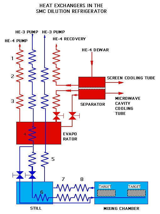
This schematic flow diagram
shows the arrangement of 8 different heat exchangers
- 4He vapour at atmospheric pressure is taken from a phase separator to precool the incoming 3He in a parallel tube counterflow heat exchanger (No. 1 in the figure) .
- This is also in thermal contact with the low-pressure 3He and 4He in a 4-flow heat exchanger (No. 2).
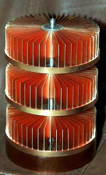
Fin type exchangers have been chosen to give reasonable pressure drop with high gas flow at low pressure. These exchangers form a conical assembly that is inserted into the precooling tower.
- The evaporator volume is 27 liters, which gives ample space for a 3He condenser and provides good tolerance to sudden heat loads without risk of drying up.
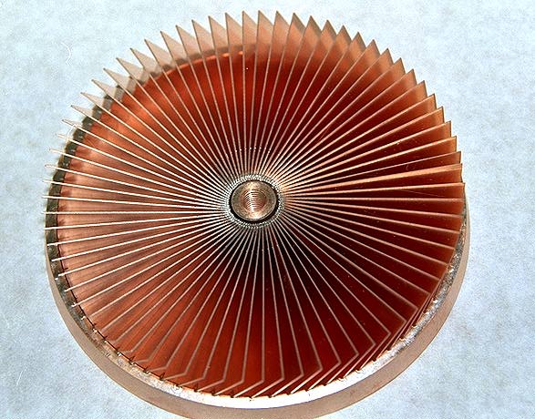
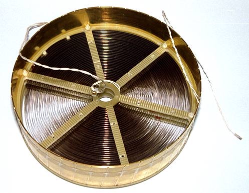
- The incoming 3He is precooled in a copper grid type heat exchanger (No. 3); such an exchanger is also used to cool the 4He liquid from the separator. This reduces the 4He boil-off rate by up to 30%. During initial cooldown the heat exchanger has to be bypassed.
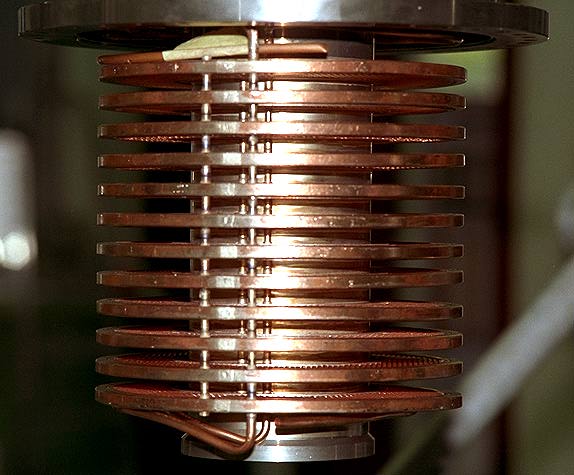
- The condenser (No. 4), made of copper tubes with inner surface area of 0.35 m2, was found to be sufficient in operation. Between the condenser and the Joule-Thompson needle valve a fin/grid type heat exchanger is placed in the still pumping tube (No. 5).
- The still has two main volumes, the lower one containing a tubular heat exchanger for incoming 3He and the upper one a heater and a level gauge. The heat exchanger (No. 6), made of copper tubing, has surface areas of 0.12 m2 and 0.23 m2 for the rich and the dilute phases, respectively.
The still heater is made of stainless steel strip, placed vertically and having a surface area of 0.58 m2. At the maximum design flow of 500 mmol/s about 16 W of heating power is needed, corresponding to a power density less than 3 mW/cm2 to avoid film boiling. No special precautions were taken to suppress the superfluid film flow in the still pumping tube, as the estimated film flow rate is much smaller than lowest practical 3He flow rates.
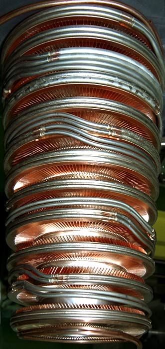
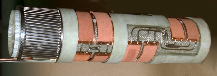
- Between the still and the mixing chamber a tubular (No. 7) and a sintered copper (No. 8) heat exchanger are placed into a helicoidal groove formed by glassfibre-epoxy spacers. The helicoidal groove defines also the dilute phase flow channel. A machined stainless steel tube with tight fitting to the spacers seals off the flow channel. The length of the flow channel along the centerline is 1.7 m and the free cross-sectional area is about 11.5 cm2. This heat exchanger is also bypassed during initial cooldown.
The main purpose of the tubular heat exchanger is to condense vapour bubbles which may have formed in the flow at the expansion needle valve and to cool the helium below the phase separation temperature before entering the narrow channels of the sintered heat exchanger. The unit is made of flattened stainless steel tubes and has a total inner surface area of 0.1 m2.
The sintered heat exchanger consists of 12 elements with overall dimensions of 120 x 40 mm2 arranged in two parallel flows. As the viscosity of 3He increases rapidly below 0.5 K, the flows are crossed at several points to prevent cold fluid plug formation. The base material is 0.2 mm phosphor copper foil. The elements consist of two sintered plates which were first bent to fit into the flow channel and then electron beam welded together. The average thickness of the layer of the nominally 18 microm grain size sinter is 0.75 mm, yielding to 375 g of sinter and a geometrical surface area of 12 m2 on both the concentrated and the dilute phase sides. The sinter surface is grooved to increase the interfacial area with fluid flow and to produce turbulence on the concentrated side to enhance heat transfer.
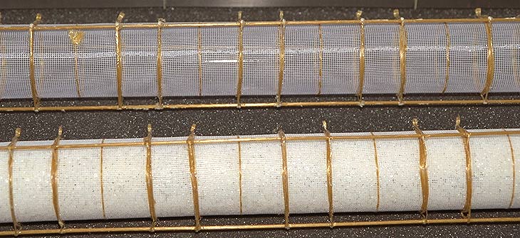
The Mixing Chamber and The NMR Coils
The mixing chamber, with a length of 1500 mm and a diameter of 70 mm, is made of glassfiber reinforced epoxywith 0.6 mm wall thickness to ensure sufficient rigidity and to withstand slight overpressures in the case of a pump failure.
The Target Holder
The vacuum chamber has two 0.1 mm stainless steel windows for the beam access and 6 aluminium foil thermal shields, and it provides thermal anchors for the coaxial lines for NMR and for the instrumentation wires.
The plastic part is mostly made of Kevlar-epoxy composite for rigidity and reduced thermal contraction. The target has two identical cells with a length of 650 mm and a diameter of 50 mm. Vertex resolution requires a gap of 200 mm between the halves.
The net volume of the target is 2x800 cm3. Good convectional heat transfer is assured by making the target containers of polyester net with 60% open area. The containers weigh only 30 g each; the NMR signal from the protons in the target holder was measured to be only 1% of the size of the thermal equilibrium signal of the protons in target material at 1 K.
To ensure uniform temperature, 3He is fed into the mixing chamber through 40 holes in a CuNi tube which is fixed to the container support. A spring-loaded conical connector couples the outlet of the main heat exchanger to the CuNi tube when the target holder is in place.
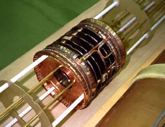
The Microwave Cavity and Microwave Stopper Construction
- The mixing chamber is surrounded by a cylindrical microwave cavity of 210 mm in diameter, made of copper.
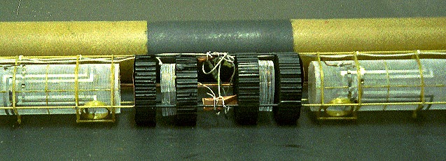
- The cavity is divided axially in two compartments by placing graphite foil coated copper baffles and copper reflectors in the center.
- Inside the mixing chamber isolation was obtained using graphite coated Nomex honeycomb absorbers and fine copper mesh reflectors, designed to ensure free diffusion and convection in the dilute solution.
- The microwave isolation was measured to be 20-30 dB in the 69-70 GHz band with empty cavities; this prevents the microwave power from leaking excessively from one side of the cavity to the other.
- The cavity is cooled to 3 K by 4He flow controlled by a cold needle valve.
- The two wave guides feeding the cavity enter the main vacuum through round FEP windows and continue with circular sections made of silvered thin-walled cupronickel tubing. Rectangular guides are soft soldered to the cavity wall, and tapered slots provide coupling along the target lengths. FEP windows close the guides before the coupling slots, isolating the cavity vacuum from the main vacuum and preventing the loss of 3He in case of mixing chamber rupture.
 peter@neuro.hut.fi
last modified 11.3.95