The LED monitoring system for HCAL1 is based on single ultra bright blue (470nm) LED and optical fibers system to transmit the light to PM's.
The LED light is distributed into 484 channels by plastic optical fibers series PFU-CD 1001-22E with black PE Jacket. The diameters of the plastic kern from PMMA (organic glass) is equal 1mm. The fibers outer diameter is 2.2mm.
The light from the single LED is distributed in two steps: At the first step the light is distributed between 34 fibers, out of which at the second stage 30 fibers distribute the light between 16 fibers each, i.e. 480 channels, and 4 fibers from the first stage go to PIN-diode. The PIN-diode is used to monitoring the LED light.
The LED of the type MARL-110106 (Farnell code 884-923) with diameter 5mm and maximal light intensity 4-5mkd is used.
The LED is flashed by avalanche generator pulses, 35ns in length and 10-15V in amplitudes. The avalanche generator is activated from the artificial trigger out of spill (or in) with frequency 10-30 pulses per second. The frequency of the HCAL1 artificial trigger is selected automatically for every run from DAQ menu or manually with the scripts from any COMPASS on-line PC's:
The digits = 13 is the TCS number; = 30 is the pulse rate per second.
In general, the LED plots can be obtained via COOOL selecting CALIBRATION_EVENT type in main menu.
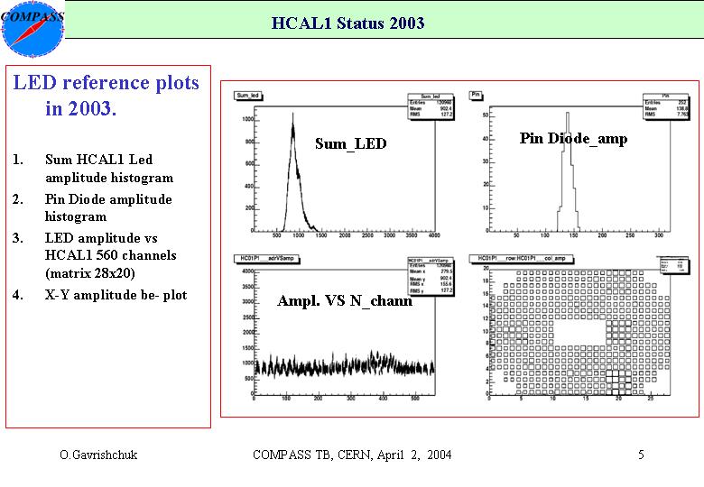
To controlled HCAL1 long time stability one can use the LED references table. The LED references table can be obtained at the start of data taking after the last HCAL1 calibration in muon halo beam.
To obtain normalized or not normalized LED amplitudes one can use the ~/onl/hcal1/referens/norm or ~/onl/hcal1/referens/ref scripts, respectively.
After this the script ~/onl/hcal1/source led @pccoebNN: should be applied to start the monitoring program, where NN is from 09 to 21.
Normalization to the LED references table allow to controlled HCAL1 stability in time by eyes loading the configuration file ~/onl/hcal1/led.cfg if monitoring program is proceed.