ptread HOWTO
information in this document is preliminary
April 7 2014 Jaakko Koivuniemi, Jan Matousek
This HOWTO explains the use of Perl scripts in the
ptread package for reading instruments with serial connector and/or
GPIB bus. The ptread is run as a daemon, it has a configuration file
and it writes messages to a log file. The ptread calls the different
instrument scripts in the schedule given by the configuration file. The data
can be written to the local disk and SQLite and/or MySQL database. The MySQL
database can be used in the popular LAMP (Linux-Apache-MySQL-PHP/Perl/Python)
architecture [1].
A customized DIM server daemon ptdimserv can be used to publish
the data for a SCADA system [2].
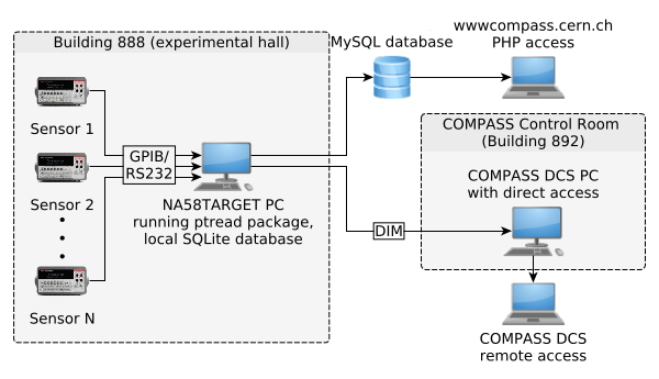
Fig. 1: ptread data flow diagram.A Linux computer is running
the ptread scripts. This computer has the necessary hardware for
the serial connections - typically with build-in RS232 ports or plugged
in USB to serial converters. It needs to have a card or an external
USB/GPIB device for the GPIB connected instruments.
Data can be stored locally in SQLite
database, send to MySQL database and published by DIM server for COMPASS DCS
(PVSS).
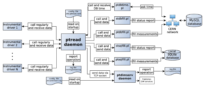
Fig. 2: Diagram of ptread operation. The ptread and the ptdimserv
programs run as daemons. Ptread calls instrument drivers to read the sensors and
then database writing scripts. Also sends data to ptdimserv, which maintains DIM
services corresponding to the sensors and keeps them updated.
The ptread provides remote access to temperatures,
pressures, flows and other parameters of the polarized target.
These parameters are then readable with the COMPASS DCS system
[3] using
process visualization and control software PVSS [4].
While the PVSS integrates well with the PLCs and field buses, it does not
support direct reading of typical laboratory instruments with a serial
connector or GPIB bus. One way of communication between the data providers
and the PVSS system is by Distributed Information Management System (DIM)
[5].
This is similar to the industry standard OPC [6].
The data flow is shown in Fig. 1.
Instruments are connected to the computer with GPIB or serial
connectors. The data is published with a customized DIM server
and the COMPASS DCS system runs a DIM client to read the most recent
values. The data can be optionally written into a MySQL database.
The database server can be in the same local machine where the reading
software is running or it can be in a remote machine.
In addition the data can be optionally written to a local SQLite database
and this comes without extra cost (except for the disk space).
The data is monitored normally from the PVSS screen. If the optional
local SQLite database is setup, the instrument reading can operate
autonomously without any network connection. This might be helpful in some
circumstances and provides a backup in case of network failure.
Setting up the MySQL database server allows network based access to
the data in addition to the access via the DCS system. The MySQL database
client could be a PHP script showing a snapshot of the data on a web page.
A simple script can copy the most recent parameter values with a SELECT
statement to a local file, see for example readpd(1) or monitorpt(1)
which can also do plotting with python-matplotlib.
The components of the ptread package and their relations are shown
in Fig. 2.
The instrument drivers are usually written in Perl. The use of
IEEE-488 bus (GPIB) requires PCI board inside the computer
or an external USB GPIB device supported by the
Linux-GPIB package [7].
If a serial connector is provided
by the instrument, the driver should support it too for the best flexibility.
The advantage of the serial connector is that it can use the build-in RS232
connector in the computer or an economical USB to serial converter for example
based on FTDI chips [8].
Check the README file of the ptread before
adding a new instrument driver script.
The configuration file /etc/ptread.conf
defines the instrument reading commands with options, the list of
the parameters and reading intervals. The operation of the daemon is
reported to /var/log/ptread.log. The parameter values are
written to a local directory typically in /var/lib/ptread/values/ and
sent via TCP socket connection to the ptdimserv(1) daemon.
The ptdimserv daemon sets up a DIM server when it starts and then it receives
messages from the ptread and publishes the new data. The parameters to be
published and program settings are in a configuration file
/etc/ptdimserv.cfg, the operation is reported to
/var/log/ptdimserv.log. Useful code for the configuration files for the
ptread and ptdimserv can be generated by the instsetup(1) script from a setup
file (e.g. in the 'setup/DrellYan' directory).
If the local SQLite database name is defined in the configuration file,
the ptsqlfill(1) and stsqlfill(1) scripts are called to insert the data into
corresponding tables. In similar way the ptdbfill(1) and stdbfill(1) scripts
are called to fill the MySQL database. The MySQL database time is checked
periodically and compared to the local computer time with ptdbtime(1).
The same script can also read the most recent time stamp from different
data tables. This information can be used in the database writing latency
estimate for example.
Installation is explained in the README file.
The unix manual pages of different programs are in 'doc' directory.
These can be read with man ptread.1 or less ptread.txt
for example or after installation with man ptread.
To start the ptread daemon use
sudo /sbin/service ptread start
It might be useful to monitor the log file during the start up with
tail -f /var/log/ptread.log or the error log file with
tail -f /var/log/ptreaderr.log.
The program creates first temporary file names for reading values from
different instruments. Then the interfaces are optionally initialized
and communication is tested. If MySQL database is used its time is asked
with a SELECT statement and compared to the local computer time. Then
the status of all the instruments is read and written to the log file.
When all these steps were done successfully
the ptread is daemonized and the main scanning loop is started.
To stop the ptread daemon use
sudo /sbin/service ptread stop
To reload the configuration file /etc/ptread.conf after editing it use
sudo /sbin/service ptread reload
The instrument drivers are command line applications written in
Perl. The connection to each instrument can be tested separately
from unix shell before attempting to run the ptread daemon.
In case of instrument failure or change in operation mode,
the driver program can be commented out from the configuration
file. It is also possible to stop the ptread daemon and try to get
back the control of the instrument by sending reset or other commands to it
with its instrument driver script.
The main purpose of the instrument driver is the reading, but it
can also be used to set some instrument parameters remotely.
The instrument drivers can print short status summary. This is useful in
checking that the instrument is working normally and to see any possible
alarms on the instrument.
The printed output format can be switched from a list of comma separated
values to more human readable format.
Common options/switches used
(without options help message is printed):
- -d serial port, e.g. /dev/ttyUSB0 or /dev/ttyS0
- -b serial port baud rate, e.g. 4800
- -g GPIB board number (minor), primary address, secondary address,
timeout, end of transmission, end of received string
- -V print version and exit
- -v verbose output, useful for debugging and trouble shooting
- -i print device status info
- -S simulate serial communication without opening the port
- -T test serial connection by sending a string and reading it back
- -C clear serial input buffer with < ETX > (Ctrl-C)
- -c send command to the instrument.
Other options may differ between the scripts. Option -t in some drivers
sets a custom timeout for waiting on instrument response.
The instrumental languages including SCPI are usually not case-sensitive.
3.1. Picowatt AVS-46 resistance bridge
| Range | Excitation level |
| 1 | 2 ohm | 1 | 10 uV |
| 2 | 20 ohm | 2 | 30 uV |
| 3 | 200 ohm | 3 | 100 uV |
| 4 | 2 kohm | 4 | 300 uV |
| 5 | 20 kohm | 5 | 1 mV |
| 6 | 200 kohm | 6 | 3 mV |
| 7 | 2 Mohm | - | - |
|
Table 3.1: Range and excitation for AVS-46
|
C++/DIM:
- range (int)
- excitation (int)
- resistance (float)
Resistance value in ohms, range and excitation level used during the measurement. Ranges and excitations are shown in table 3.1.
AVS-46 is a resistance bridge for sensitive four-wire low-temperature
resistance measurements. It is a low-noise device and uses very small AC
excitation to minimize parasitic heating of the measured resistor. It is
designed especially for very-low-temperature thermometry. It is used to
read cryogenic thermometers of the dilution refrigerator.
To connect AVS-46 with computer the interface unit DC900 is needed.
The digital interface is isolated from the bridge to cut down noise.
3.2. Picowatt AVS-47-B resistance bridge
| Range | Excitation level |
| 0 | open | 0 | none |
| 1 | 2 ohm | 1 | 3 uV |
| 2 | 20 ohm | 2 | 10 uV |
| 3 | 200 ohm | 3 | 30 uV |
| 4 | 2 kohm | 4 | 100 uV |
| 5 | 20 kohm | 5 | 300 uV |
| 6 | 200 kohm | 6 | 1 mV |
| 7 | 2 Mohm | 7 | 3 mV |
|
Table 3.2: Range and excitation for AVS-47-B
|
C++/DIM:
- number of averaged measurements (int)
- overload (overrange) flag (int 0/1)
- range (int)
- excitation used (int)
- resistance (float)
- standard deviation (float)
Resistance value and standard deviation are in ohms.
Ranges and excitations can be found in table 3.2.
AVS-47-B is a resistance bridge for sensitive four-wire low-temperature
resistance measurements. It is a low-noise device and uses very small AC
excitation to minimize parasitic heating of the measured resistor. It is
designed especially for very-low-temperature thermometry.
It is used to read cryogenic thermometers of the dilution refrigerator.
To connect AVS-47-B with computer the interface unit AVS-47-IB is needed.
The digital interface is isolated from the bridge to reduce noise
and interference in the measurement.
Commands are based on the IEEE-488.2 standard. They are processed
one by one. The only information accessible during any operation
(e.g. averaging) is serial poll response, which can be
checked at any time by: avs47 -s . With option -h
('human readable') the driver interprets the bits signalizing device
status (e.g. idle, scanning, scan delay...). Instrumental reset can be done by
avs47 -P .
Sending commands to the device is done by option
-c command(s). If any command is a query (ends with '?'), the
driver reads response. The device can accept series of commands, separated
by semicolons. The driver substitutes commas for semicolons
before it sends the command, so you can write comma-separated commands and
omit quotes. The space between command and parameter is optional.
Useful tips:
- Measurement is done by first activating the ADC and then reading
the result:
avs47 -c ADC,RES? .
- Average, standard deviation, maximum and minimum of n measurements:
avs47 -c AVEn,AVE?,STD?,MAX?,MIN? -H (-H option can be used to
see headers of the returned values).
- You have to activate the remote mode by sending REM1, before you can
modify any parameter of the measurement (not needed for reading-only
operations)
- Choose the right input (INP 0... ground, INP 1... measurement, INP 2...
calibrating resistance).
- Measurement settings: MUX [0-7]... multiplexer channel, ARN [0,1]...
autorange, RAN [0-7]... range, EXC [0-7]... excitation.
Example:
avs47 -c REM1,MUX1,EXC2,ADC,RES?
- You can query practically any parameter (MUX?, INP?, REM?...) and with
option
-h get human readable response (e.g. '2 Mohm',
'manual mode'...) for most of the queries.
- Stop averaging by sending STP.
- By setting correct range in autorange mode you can save
time (stabilization delays needed after range-switching).
- Scan through channels using driver switch
-m ch1,exc1,del,ran,cnt/... The parameters for each channel
(channel number, excitation, stabilization delay, range and number of averages)
are separated by commas, parameters for next channel follow after slash.
For human readable output use with -h -H ,
for ptread daemon with -d .
Output is average value, standard deviation
and used settings (see man avs47 or try yourself).
The example of usage in ptread:
- Print status information:
avs47 -i -h
- Measure channel 0 and print used settings, all comma-separated:
avs47 -m 0,3,8,4,5 -d
For more information check the device manual and man avs47.
3.3. Phase Matrix EIP-548-B frequency counter
C++/DIM:
- status byte (int 0-127) (One can get bit n of x usually by (x&n)/n)
- equal to 0 ... OK
- bit 4 is 1 ... reading register overflow
- bit 2 is 1... no signal on input
- frequency in Herz (float)
The counter is used to measure frequency of the DNP microwaves.
The instrument supports SCPI, but measurement parameters can be only set,
not queried.
3.4. Siemens Multireg C1732
C++/DIM: Unspecified, this instrument probably won't be used.
Channel number, measured value, suffix, first limit, second limit and warnings.
32-channel programmable acquisition unit and plotter. Can also control
parameters and give alarms. The program is stored in non-volatile memory
and is protected by a password. It is used to read level meters, pressure
gauges, flow meters...
3.5. HP 34970-A acquisition unit
C++/DIM: Probably just:
- Measured value (usually voltage) (float)
Multi-channel acquisition unit. Has potential to replace the Multireg in case
of problems with this rather historical but so far reliable device.
The instrument fully supports SCPI.
3.6. Keithley 2000 multimeter
C++/DIM:
- Measured value (usually voltage) (float)
Digital multimeter. Used to measure microwave power
The instrument fully supports SCPI.
3.7. LakeShore 218 temperature monitor
C++/DIM:
- Temperature in Kelvins (float)
Temperature monitor used for diode thermometers.
3.8. Pfeiffer TPG-262 pressure display
C++/DIM:
- status (int 0-6)
- 0 ... Measurement data ok
- 1 ... Underrange
- 2 ... Overrange
- 3 ... Sensor error
- 4 ... Sensor off (IKR,PKR,IMR,PBR)
- 5 ... No sensor
- 6 ... Identification error
- Pressure (float)
Pressure display unit.
The DIM server daemon ptdimserv is started/stopped with
sudo /sbin/service ptdimserv start/stop
To reload the configuration file /etc/ptdimserv.conf after editing it use
sudo /sbin/service ptdimserv reload
The DIM parameter service is updated when the daemon receives message from
ptread via TCP socket. The DIM DNS has to be running on localhost or some other
machine (the host can be set in the configuration file) for the DIM services
to be accessible.
The ptdimserv is written in C++ and needs to be compiled in the host
machine. This is done by first editing the dim/Makefile and then running
make. See the dim/README on how to install the libdim dynamic
libraries. The manual pages ptdimserv(1) and instsetup(1) explain how to
generate the list of parameters for the configuration file. A sample
configuration file is in the 'dim' directory.
See the README file.
AVS 46:
For the cable one 25-pin male and 9-pin female sub-D connector is needed. These are connected with three wires as follows:
AVS 46 DC900 25-pin PC 9-pin female
PIN 2---------------------------PIN 2 (RXD input)
PIN 3---------------------------PIN 3 (TXD output)
PIN 7---------------------------PIN 5 (GND)
The serial protocol is 1 start bit, 8 data bits, no parity and 1 stop bit.
Keithley 2000:
Straight cable with male 9-pin connector on device side, only pins 2 (TXD), 3 (RXD) and 5 (GND) are used. Wiring used for test:
Keithley 9-pin male PC 9-pin female
PIN 2---------------------------PIN 2 (RXD input)
PIN 3---------------------------PIN 3 (TXD output)
PIN 5---------------------------PIN 5 (GND)
The serial protocol is 8 data bits, no parity and 1 stop bit.
Lakeshore 218:
For the cable two 9-pin female sub-D connectors are needed. These are
connected with three wires as follows:
TPG262 9-pin connector PC 9-pin connector
PIN 2-------------------------------PIN 3 (TXD output)
PIN 3-------------------------------PIN 2 (RXD input)
PIN 5-------------------------------PIN 5 (GND)
The serial protocol is 1 start bit, 7 data bits, 1 parity and 1 stop bit.
TPG 262:
For the cable two 9-pin female sub-D connectors are needed. These are
connected with three wires as follows:
TPG262 9-pin connector PC 9-pin connector
PIN 2-------------------------------PIN 3 (TXD output)
PIN 3-------------------------------PIN 2 (RXD input)
PIN 5-------------------------------PIN 5 (GND)
The serial protocol is 1 start bit, 8 data bits, no parity and 1 stop bit.
[1] https://en.wikipedia.org/wiki/LAMP_%28software_bundle%29
(Linux, Apache, MySQL and Perl/PHP/Python)
[2]
https://en.wikipedia.org/wiki/SCADA (supervisory control and data acquisition)
[3] https://compass-dcs.web.cern.ch/compass-dcs/scripts/welcome.asp
(COMPASS DCS homepage)
[4] http://j2eeps.cern.ch/wikis/display/EN/PVSS+Service (CERN PVSS service)
[5]
http://dim.web.cern.ch/dim/ (DIM homepage)
[6]
https://en.wikipedia.org/wiki/OPC_Foundation (Object Linking and Embedding for Process Control (OPC) Foundation)
[7]
http://linux-gpib.sourceforge.net/
(Linux-GPIB package homepage)
[8]
https://en.wikipedia.org/wiki/USB_adapter
(USB serial adapters)